Frequently Asked Question
Neutral-axis mechanics
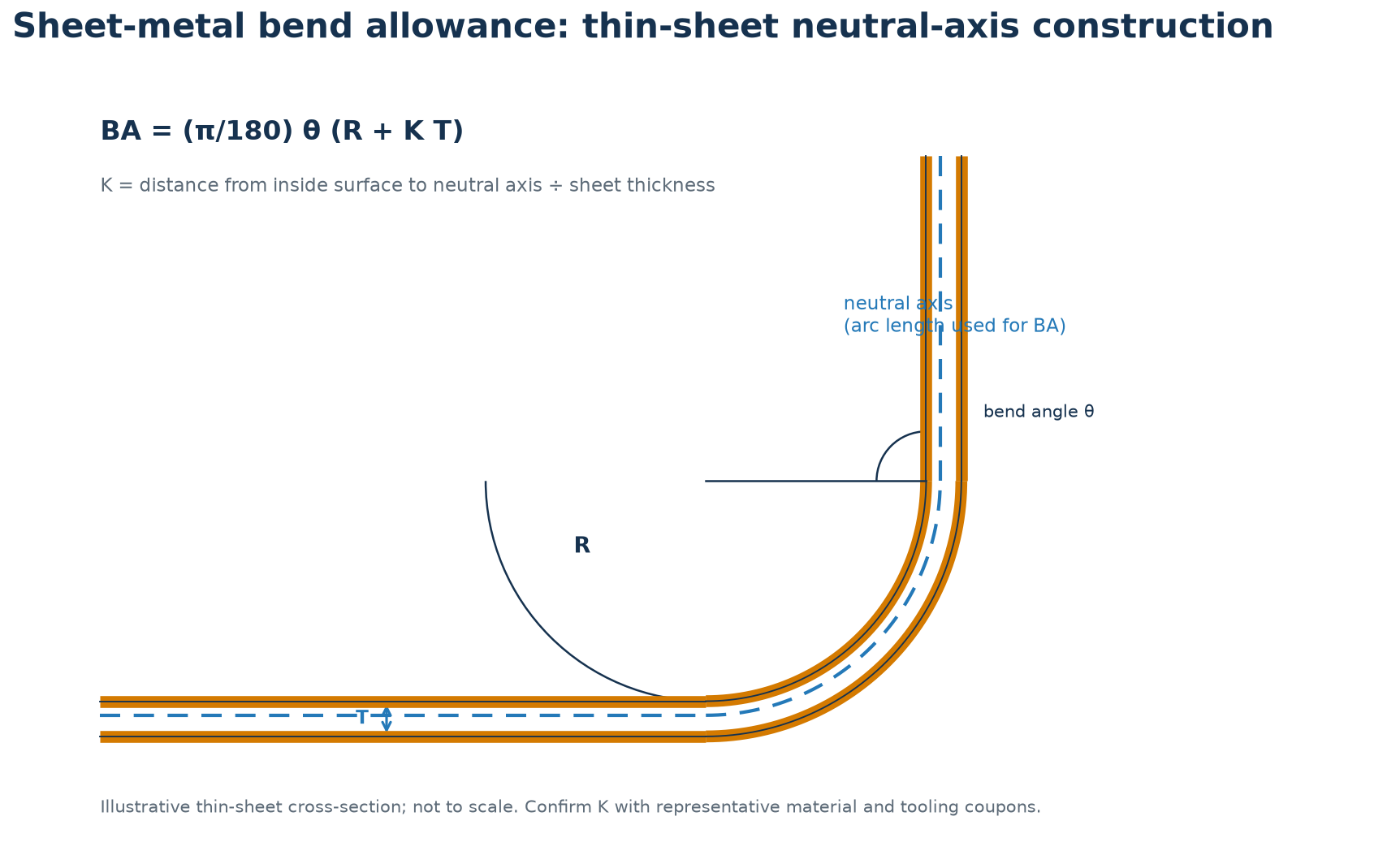
During a sheet-metal bend, fibres near the inside radius are compressed and fibres near the outside radius are stretched. The neutral axis is the layer whose length is approximately unchanged. It shifts toward the inside surface, and the K-factor represents its distance from that surface divided by material thickness. K is an empirical forming parameter, not a universal constant: alloy, temper, thickness, radius-to-thickness ratio, grain direction, die opening, friction, and forming method all affect it.
BA is bend allowance, θ is bend angle in degrees, R is inside radius, T is sheet thickness, and K is the neutral-axis fraction. Use a consistent angle and dimension convention throughout the drawing and calculation.
Worked example
For T = 2.0 mm, R = 3.0 mm, K = 0.40, and θ = 90°, BA = (π/180)(90)(3.0 + 0.40×2.0) = 5.969 mm ≈ 5.97 mm. This calculated value is a starting prediction. Make a coupon with the intended material batch and tooling, measure the formed legs and radius, and update the bend data if the measured result differs.
Calibration note: 5.65 mm would correspond to a different calibrated K of approximately 0.30 for these same R and T values; it is not the result for K = 0.40.
Limit: do not transfer a K-factor from a different material, thickness, tool, grain orientation, or forming method without checking its effect on the developed length.
Engineering check
For Sheet-Metal Bend Allowance and K-Factor, record the material condition, tool or fixture identity, process settings, measurement method, sampling plan, and reaction rule. Confirm that the measurement system is capable of resolving the requirement and that the process is stable before using capability or first-article data to justify release. Reconfirm the limits after a material, tool, or route change.